2001 Ford F350 7.3 Turbo Diesel Injector Connector Wiring Diagram
Ford F-350 (1999 – 2001) – fuse box diagram
Twelvemonth of production: 1999, 2000, 2001
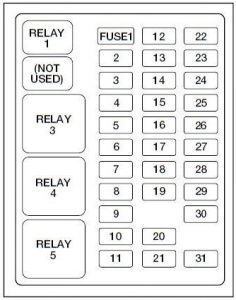
Rider Compartment Fuse Box
The fuse panel is located below and to the left of the steering bike by the brake pedal.

| Number | Ampere rating [A] | Description |
| 1 | xx | Plow/Hazard Lamps |
| 2 | 5 | 1999: Instrument Cluster, Ability train Control Module (PCM) Keep Live Memory |
| 10 | 2000: Airbag Module | |
| 3 | xx | Cigar Lighter, Information Link Connector |
| 4 | 10 | Glove Box Lamp, Map Lamps, Power Mirrors, Underhood Lamp |
| 5 | — | — |
| 6 | — | — |
| seven | five | Power Window/Lock Switch Illumination |
| viii | 5 | Radio, Headlamp Switch Illumination, Remote Anti-Theft Personality (RAP) Module (1998) |
| nine | — | — |
| 10 | fifteen | 2000-2001: Dual Fuel Tanks |
| xi | 30 | Wiper Motor, Wiper Run/Park Relay Coil, Wiper Hi/LO Relay Coil, Washer Pump Relay Coi |
| 12 | xv | Horn |
| 13 | 20 | End Lamps, Center High-mount Cease Lamp, Trailer Tow Stop Lamp, Speed Command |
| xiv | 10 | Dome Lamp, Cargo Lamp, Courtesy Lamps, Running Board Lamps |
| 15 | 5 | 1999: Generic Electronic Module (GEM), Powertrain Control Module (PCM), Anti-lock Restriction Arrangement (ABS) Module, Brake Shift Interlock, Speed Control 2000-2001: Finish Lamp Switch (Logic): Generic Electronic Module (GEM), Powertrain Control Module (PCM), Four Wheel Anti-lock Restriction System (4WABS) Module, Brake Shift Interlock, Cluster and PCM Keep Alive Memory |
| 16 | xv | Instrument Cluster, Hi-axle Headlamps |
| 17 | — | — |
| xviii | 5 | 2001: Audio |
| 19 | 10 | Auxiliary Powertrain Command Module (APCM) (Diesel fuel only), Instrument Cluster, Jewel Module, Overdrive Cancel Switch, Idle Validation Switch (Diesel only), Overhead Console, Diesel PCM via Clutch |
| 20 | 15 | Starter Motor Relay Curl, Clutch Switch |
| 21 | — | — |
| 22 | 10 | Air Bag Module (2000-2001), Passenger Air Bag Activation/Deactivation Switch, Blower Motor Relay Curl |
| 23 | x | 1999: Electronic Flasher 2001: Air Bag Module |
| 24 | x | 1999: Blend Door Actuator, Trailer Tow Battery Charge Relay Coil 2000-2001: A/C Clutch, Blend Door Actuator, Trailer Tow Batteiy Accuse Relay Coil, Four Bike Anti-Lock Brake System (4WABS), Turn Betoken |
| 25 | 5 | 1999: 4 Wheel Anti-Lock Brake System (4WABS) Module |
| 26 | — | — |
| 27 | x | Ignition Run Power Feed (Client Access) |
| 28 | xv | Restriction Shift Interlock, DRL Relay Curl, Speed Control Module, Fill-in Lamps, Trailer Tow Backup Lamp Relay Whorl, Electronic Shift On The Wing Hub Lock Solenoid, Vacuum Pump Motor |
| 29 | five | Instrument Cluster (Charge and Airbag Alert Lamps) |
| 30 | 30 | PCM Relay Curl, Ignition Coil (Gasoline but), Fuel Heater (Diesel only), Wastegate Solenoid (Diesel just), Injector Driver Module Relay Coil (Diesel fuel only) |
| 31 | 5 | 2001: Fog Lamp Switch |
| Relay | ||
| R1 | Interior Lamp | |
| R2 | — | |
| R3 | Horn | |
| R4 | Ability Window I Touch Down | |
| R5 | Accompaniment | |
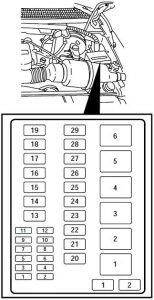
Engine Compartment Fuse Box

| Number | Ampere rating [A] | Description |
| 1 | vii,five | 1998: Trailer Tow Left Cease/Turn Lamp |
| 2 | x | 1999: Air Bag Module 2000-2001: Washer Pump |
| three | vii,v | Trailer Tow Right Terminate/Turn Lamp |
| 4 | twenty | Trailer Tow Backup Lamps, Trailer Tow Park Lamps |
| 5 | 20 | Gasoline: PCM, Fuel Pump Relay Coil, Mass Air Catamenia Sensor, Fuel Injectors |
| 5 | Diesel: Dual Alternator "A" Field | |
| 6 | x | Gasoline: A/C (CASS) Diesel: Unmarried or Dual Alternator "A" Field, Regulator |
| 7 | 20 | Gasoline: Vapor Management Valve, HEGO Sensors, Intake Manifold Communication Control, EVR Solenoid, PCM, Canister Vent Solenoid |
| five | Diesel: Dual Alternator "A" Field | |
| viii | 15 | Trailer Tow Electronic Brake Illumination, Park Lamps, Trailer Tow Park Lamp Relay Coil |
| 9 | 10 | Left Headlamp (Low Axle) |
| 10 | 25 | 1999: Power Point |
| 20 | 2000-2001: Power Bespeak | |
| eleven | 10 | Right Headlamp (Low Axle) |
| 12 | 10 | 1999: Daytime Running Lamps (DRL) Resistor |
| 15 | 2000-2001: Daytime Running Lamps (DRL) Resistor, Fog Lamps | |
| 13 | thirty | Multi-function Switch, Headlamps |
| xiv | 60 | Anti-Lock Brake Arrangement |
| 15 | 30 | 1999: Windshield Wiper Motor 2001: Heated Seats |
| 16 | 30 | Trailer Tow Battery Charge |
| 17 | 30 | Electronic Shift On The Fly Relay, Transfer Case Shift Motor |
| 18 | 30 | Power Seat, Adjustable Pedals (2001) |
| 19 | 20 | Fuel Pump Motor, PCM |
| twenty | 50 | Ignition Switch (B4 & B5) |
| 21 | 50 | Ignition Switch (B1 & B3) |
| 22 | 50 | Junction Box Fuse/Relay Panel Battery Feed |
| 23 | 40 | Blower Motor |
| 24 | 30 | 1999: Ability Distribution Box 2000-2001: Gasoline: PCM Power |
| twenty | 2000-2001: Diesel: PCM Power | |
| 25 | 30 | Power Windows |
| 26 | twenty | If equipped with Remote Keyless Entry-Driver Door Unlock Relay Coil, All Door Unlock Relay Coil, All Door Lock Relay Roll, Park Lamp Flash Relay, If not equipped with Remote Keyless Entry-Power Door Lock Motors |
| 27 | thirty | Diesel: Injector Commuter Module |
| 28 | 30 | Trailer Tow Electronic Restriction Controller |
| 29 | 20 | Radio |
| Diode | ||
| 36 | A/C Clutch | |
| 37 | PCM | |
| Relay | ||
| 30 | PCM Ability | |
| 31 | Blower Motor | |
| 32 | 1999: Gasoline: Two Speed Fuel Pump 2000-2001: Gasoline: A/C CASS 1999-2001: Diesel fuel: Injector Driver Module Power | |
| 33 | Washer Pump | |
| 34 | Windshield Wiper Park/Run | |
| 35 | Windshield Wiper HI/LO | |
| 38 | Trailer Tow Backup Lamp | |
| 39 | Trailer Tow Battery Charge | |
| xl | Electronic Shift On The Wing #i | |
| 41 | Electronic Shift On The Wing #two | |
Warning: Terminal and harness assignments for individual connectors volition vary depending on vehicle equipment level, model, and market.
2001 Ford F350 7.3 Turbo Diesel Injector Connector Wiring Diagram
Source: https://www.autogenius.info/ford-f-350-1999-2001-fuse-box-diagram/
Posting Komentar untuk "2001 Ford F350 7.3 Turbo Diesel Injector Connector Wiring Diagram"